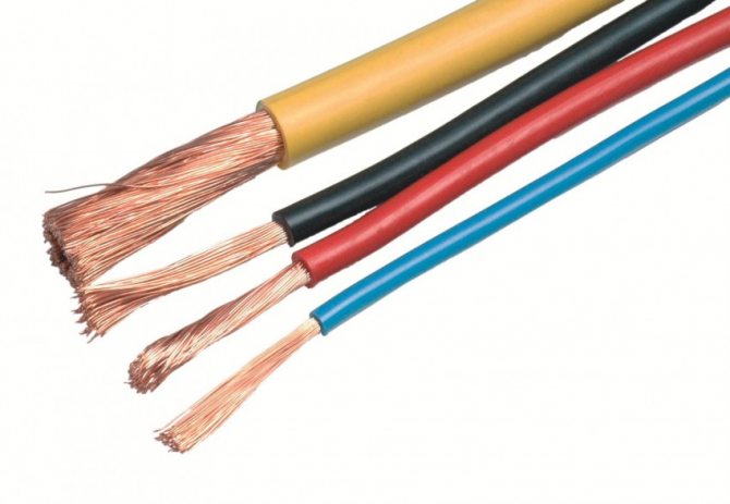
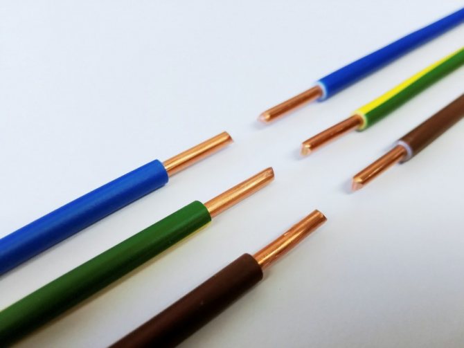
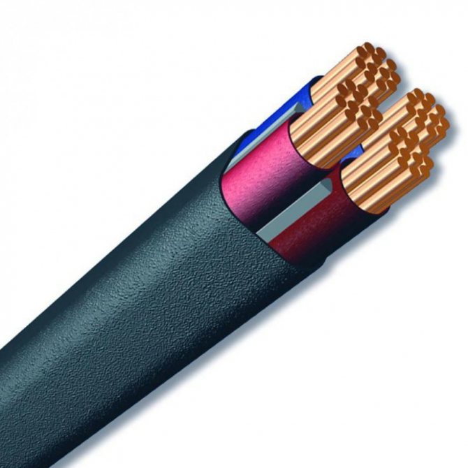
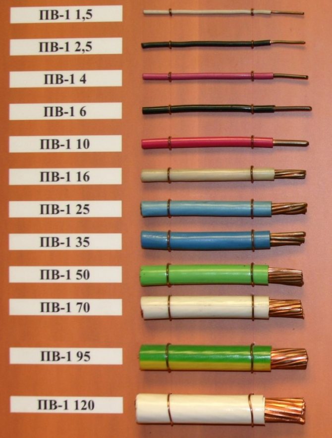
Modern dwelling is a plexus of communications, the intersection of all kinds of wires, pipes of various diameters and cables, each of which has its own purpose. The uninterrupted functioning of household electrical appliances and inter-house communications depends on the reliability of the electrical network. Its installation and switching must be entrusted to an electrician. But, given that the process is simple, the owner of basic knowledge of the functioning of the electrical network will be able to install electrical wiring in a private house on his own.
Stages of work on the installation of electrical wiring
Installation of electrical wiring - this is the final stage of a whole range of works, which includes not only the design of the system, but also such important stages as:
- The choice of the method of laying the electric cable for a given type of power supply (220 or 380 volts).
- Determination of the total power for which the wiring should be calculated, as well as drawing up a diagram of the distribution of loads for individual consumer groups.
- Before starting the installation work, it is important to decide on the method of entering the power cable into the house, after which it is necessary to draw a detailed wiring diagram on the plan of the residential building.
Each of these points needs more detailed consideration. However, you should first familiarize yourself with the basic provisions of the PUE concerning the installation of electrical wiring in houses located outside the city.
Safety rules for the installation of the electrical network
Follow these guidelines:
- Any work must be carried out with the stress relieved.
- Do not damage any part of the cables or plugs.
- All hand tools must have insulated handles.
- When installing at long distances, for example, under the ceiling, you need to erect stable structures or use special ladders, and not stand on tables or chairs.
- It is better to work not alone, but with an assistant, so that, if necessary, he can provide first aid. How to do this is shown in the figure:

Installation rules according to PUE
Requirements PUE-7, chapter 2.1. "Electrical wiring" the following provisions are negotiated and regulated regarding the wiring of electrical wiring in a private house:


Electrical Code (seventh edition)
- The method of input (via an overhead line or via an underground cable), as well as parameters that determine the distance from the post outlet to the house and the height of the self-supporting insulated wire cable (read more below).
- The rules also stipulate the choice of the type of wire used for wiring power lines in all rooms and a standard set of electrical installation products (junction boxes, switches, sockets, etc.).
- In addition, they contain instructions on the procedure for choosing power switching, protective and accounting equipment (switchboard, electricity meter and AV machines).
The rules of the PUE also stipulate such important issues as compliance with safety measures during electrical wiring.
These and other basic rules for wiring will be discussed in detail in this article.
Which way of laying to choose
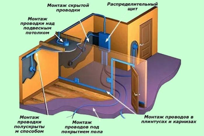
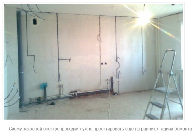
It is known that according to the method of laying electrical wiring inside the premises, it is divided into two types: hidden and open. The first of them is organized in the thickness of the walls, for which special grooves, called grooves, are prepared in them.
Installation of hidden wiring
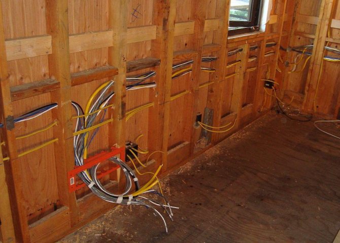

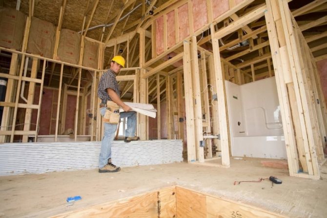
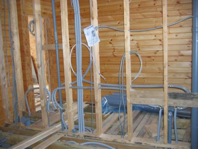
Installation of hidden electrical wiring in a frame house
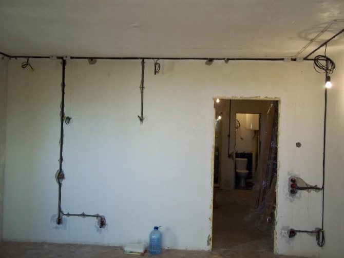

Wiring is mounted in grooves cut in the plastered room
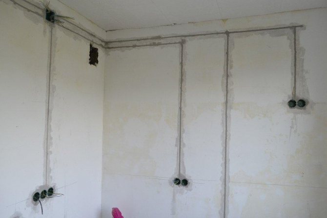

Wiring is mounted in grooves cut in the plastered room
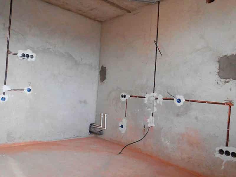

Wiring is mounted in grooves cut in the plastered room
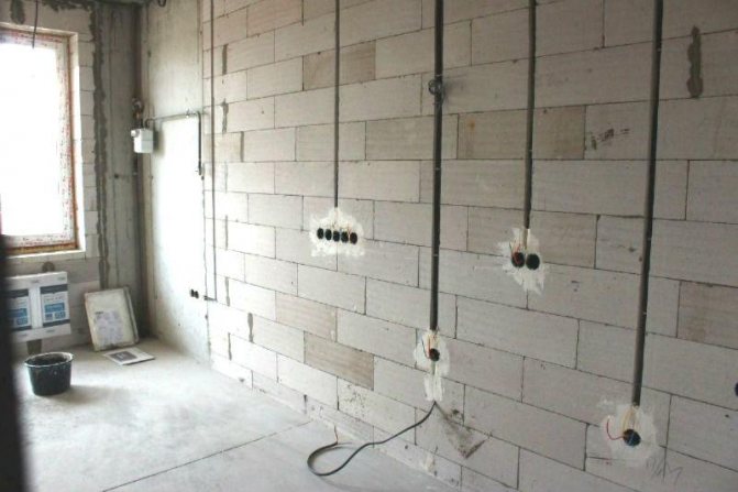

Electrical wiring in grooves made in foam blocks
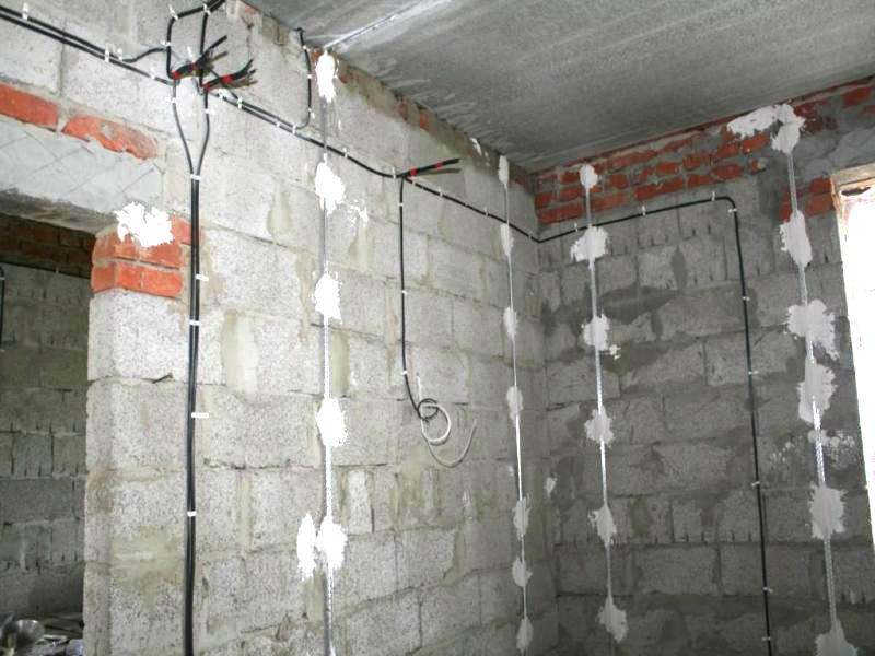

Installation of electrical wiring on cinder blocks
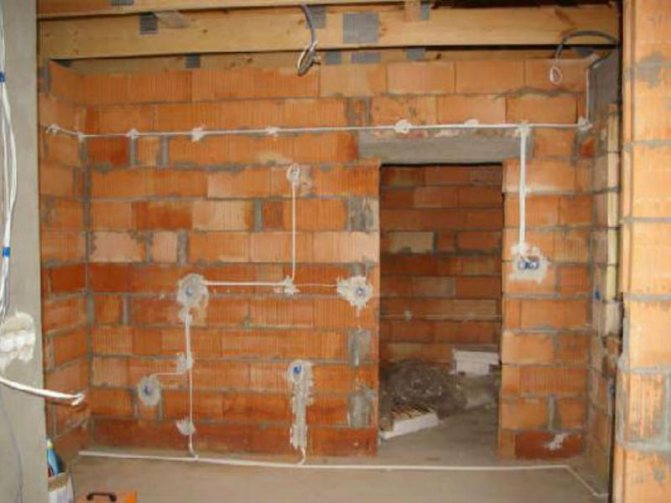

Installation of electrical wiring before plastering
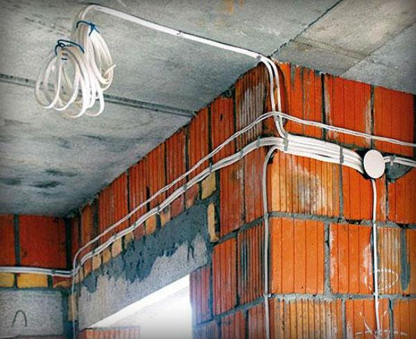

Installation of electrical wiring on brick before plastering the walls
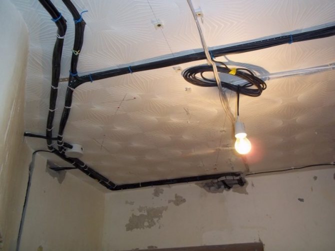
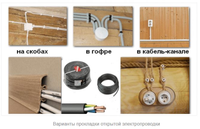
The second type differs from the first in that in this case the wires are laid directly on the surface of the walls or placed in special plastic (metal) casing-channels. If desired, the cable conductors can also be routed in a corrugation made of synthetic material. This option is also referred to as outdoor installation methods traditionally used in houses built on the basis of flammable materials.
Installation of open wiring
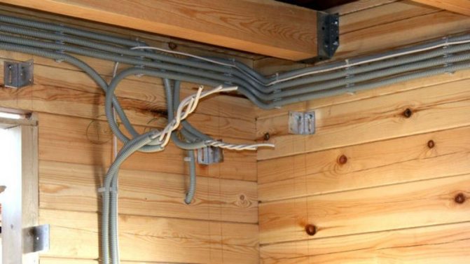

Installation of electrical wiring in a plastic corrugation
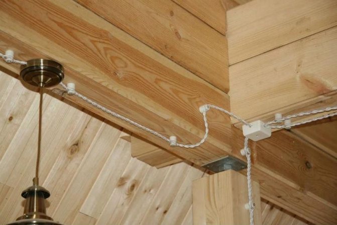

Retro wiring in a wooden house
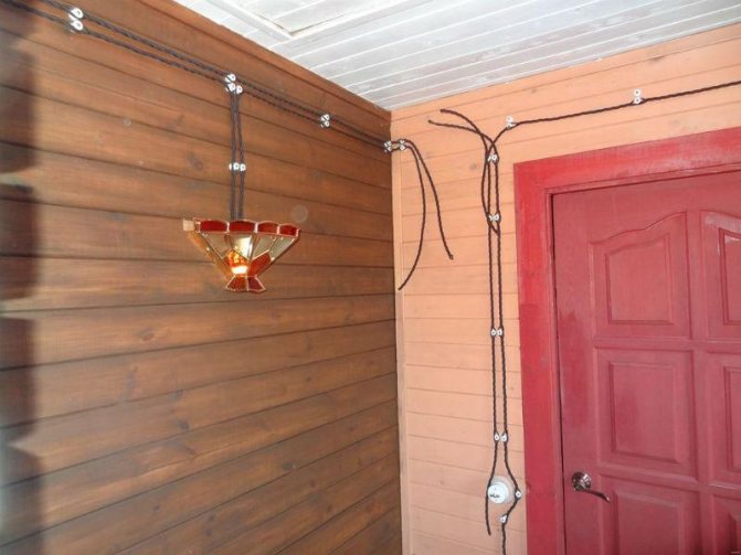

Retro wiring installation


Retro antique wiring
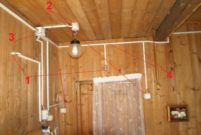

Typically, in cable ducts, wiring is mounted in production facilities
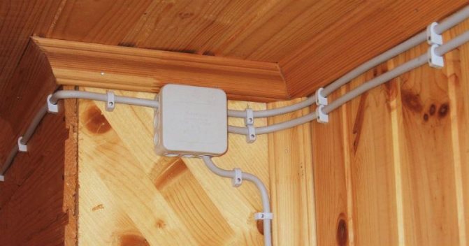

Wiring in plastic pipes
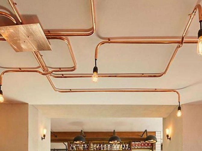

The electrical wiring in the pipes fits in the original interior


This wiring design fits perfectly into the interior
All the listed means of protection according to the PUE are allowed to be used when arranging open wiring in a private house. A completely different matter is a hidden gasket, the arrangement of which requires a lot of effort and a lot of time.
Please note: If the walls of a country house are plastered, a strong dustiness of the room will be added to the difficulties of making grooves during the work.
The latter circumstance forces the performer to work in a respirator with his own hands when arranging electrical wiring in the house or to use a powerful household vacuum cleaner.
In case of hidden wiring in accordance with the PUE clause 2.1.49, the wire must be protected on all sides by a structure made of non-combustible materials with a thickness of at least 1 centimeter. If work is carried out in buildings with walls made of non-combustible materials, wires or cables may be laid without protective covers. They fit into the already prepared grooves in the form of a bundle or are attached over a brick or block wall, and then covered with a layer of plaster.
The hidden method of wiring design is suitable, as a rule, only for living rooms. There are some restrictions for office space in the PUE. So, according to clause 7.1.37, it is recommended to lay the cable in damp and especially humid rooms only in an open way. The same requirement applies to basements and attics available in any country house.
Rules and tips
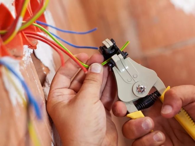

Everything related to electrical work is regulated by the Code of Electrical Installation Rules (PUE). For those who are seriously involved in the installation of electrical wiring, it is useful to get acquainted with this book at your leisure. Here we will give the most basic and important points that must be taken into account before doing the wiring in the house with your own hands:
- All junction boxes, sockets and switches should be easily accessible (not covered with wallpaper, not hidden under drywall sheets, not crammed with bulky furniture that cannot be moved).
- The grounding conductor must be bolted to the appliances.
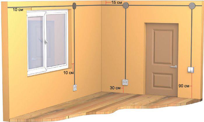
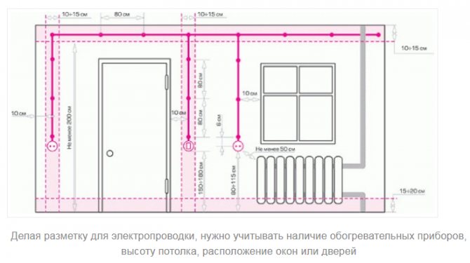
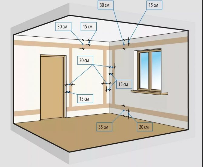
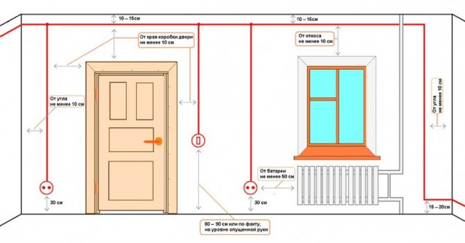
- The switches are mounted at a height of 60-150 cm from the floor level, the wires are brought to them from top to bottom.
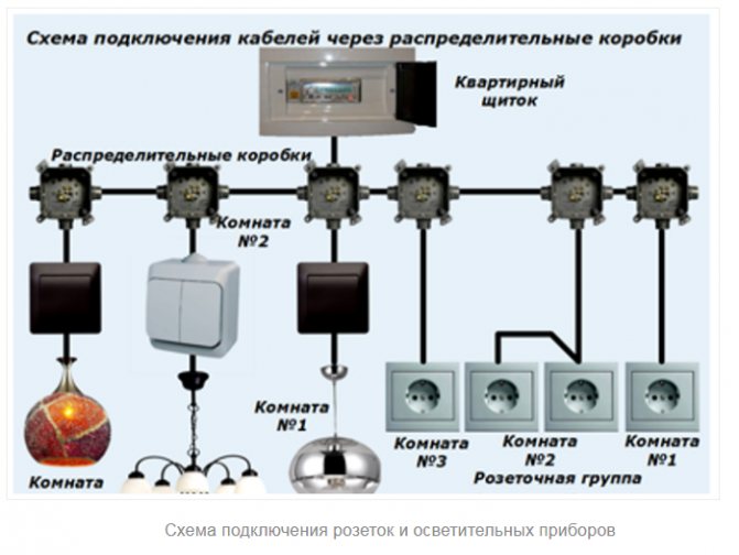
- All wire connections should be made in junction boxes. The connecting nodes must be reliably insulated; it is forbidden to connect copper conductors with aluminum ones.
- The sockets are mounted at a height of 50-80 cm from the floor level. The distance between sockets and gas stoves, pipes, heating radiators should not be less than 50 cm.
- The wires of the electrical wiring must not touch the metal building structures of the building (especially for hidden wiring, be sure to take this point into account when you lay the wires in the grooves).
- The number of sockets per room is taken into account at the rate of 1 switching device per 6 m2 of area. The exception is the kitchen, you can mount as many sockets on it as you need to connect all household appliances.
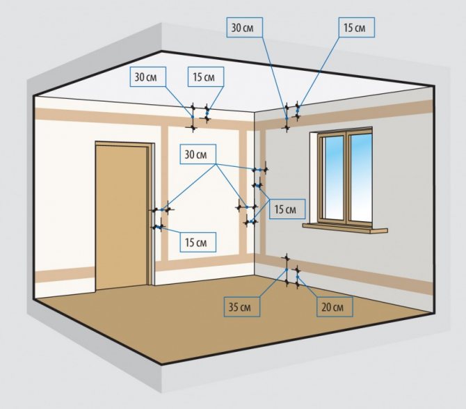
- The horizontal laying of wires is made no closer than 15 cm to the ceiling and floor. The wires are placed vertically at a distance of 10 cm from door and window openings. The wires of the electrical network must not be brought closer to gas pipes closer than 40 cm.
We hope that this whole conversation was not in vain. You will definitely start the installation of external and internal power supply to your home by drawing up a diagram. Think with the whole family where and what kind of equipment you want to place, put everything on paper, draw all the switching devices and wiring routes. This will make it much easier to calculate the amount of materials needed. Then all that remains is to transfer your scheme from paper to real walls and do the installation work.
How many phases to choose for a private house
The choice of the type of food for a suburban residential building depends on the following factors:
- Does the owner of the house intend to install power equipment in it like a woodworking milling machine, for example.
- Will he need to connect to the network units containing 3-phase asynchronous motors (including pumping stations and similar machines).
- Does he plan to buy other equipment in the future that can only operate on a three-phase 380 volt power supply.
If the answer is yes to at least one of these questions, the owner of the house must obtain permission to arrange the appropriate connection to the high-voltage line. To obtain official confirmation from Energosbyt, the owner of a private farm must provide convincing arguments with the calculation of the required full capacity.
Determination of the total power
When designing electrical wiring in a private house, special attention is paid to such an important parameter as the indicator of energy consumption. To calculate the power required for a private house, you will need to take into account all loads connected to the supply line at the same time. When calculating this indicator, the following important points are taken into account:
- the maximum power at a given voltage in the network is determined by the corresponding value of the current in the load;
- on the other hand, for each individual consumer, this parameter can be found from the documentation attached to it (passport, in particular);
- to obtain the calculated value, it is enough to add up all the currents flowing in the loads and multiply them by the mains voltage (220 or 380 volts);
- if there are passports for household appliances and power equipment, the power indicators indicated in them are summed up.


Table of power consumption and current strength of household electrical appliances at a supply voltage of 220V
Important! By the known value of power consumption, you can yourself determine the amount of current that will flow in the load when this device is connected to the network.
This possibility is explained by the fact that the two indicators used in calculating the wiring are linked by a simple physical dependence, represented by the following formula:
P (W) = U (Volts) x I (Amperes).
How to correctly calculate the power of the line in order to lay the wiring in the house with your own hands
At the preliminary stage, you must ask the energy saving company for a certain maximum amount of electricity in order to avoid overloading the network. To evaluate this indicator, study the technical data sheets of all household devices. Below we present a table with averaged values:


Rarely all of these devices can be turned on at the same time, so engineers use such a concept as the coefficient of simultaneity. For conventional sockets, it is only 0.1-0.2, so we can assume that on average the resource is used by 10-20%. When we figured out what needs to be done indoors, let's move on to the connection stage.
Entering electricity into the house
One of the most difficult issues that one has to face when connecting a house to the power supply is obtaining permission to enter a power cable into a private building. On the part of the organizations responsible for supplying electricity to the consumer for a specific branch, in this case Energosbyt acts. In order to legally formalize this procedure, the user will first need to develop and then approve a project for the power supply of a residential building. In addition, it will be necessary to prepare technical conditions for connecting a power cable with a certain type of supply voltage.
Please note: It is very difficult to independently draw up all the necessary documentation that may be required for submission to Energosbyt.
Therefore, many owners of private properties prefer to solve this issue with the help of energy specialists.
Air line
Upon completion of all the approval procedures, you can move on to purely technical points regarding how to lay the power cable and organize the entry of electricity into the building. To do this, first of all, you will need to separately consider each of the indicated ways of connecting it (by air or in the ground).
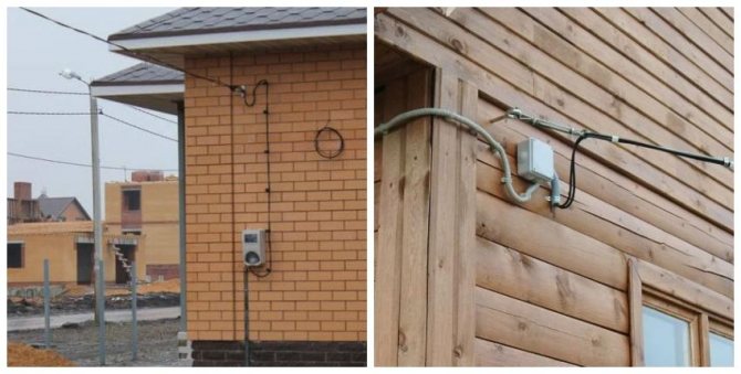

Air entry of the power cable into a private house
Additional information: In practice, in the overwhelming majority of cases, Energosbyt is ordered to carry out commissioning via an overhead line (it is easier to check for theft of electricity).
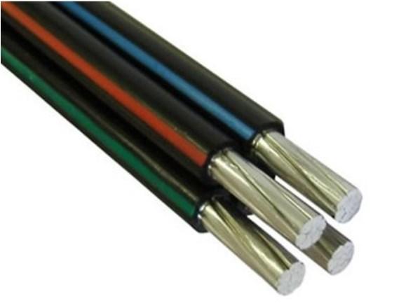

Aluminum cable SIP-4
With this method of organizing the connection in country houses, a special self-supporting wire called SIP-4 is traditionally used. The number of cores in the cable, as well as the cross-section of each of them, depend on the parameters of a particular supply network. For a typical single-phase input, it is necessary to have a two-core cable, and as a rule, wires with a core cross-section of about 16 mm2 are enough (SIP-4 2x16)... For a three-phase input, it is necessary to have a four-core cable of the same cross-section (SIP-4 4x16)... When laying it in accordance with the PUE, certain spatial relationships must be observed in terms of the mutual distance of objects, namely:
- the distance from the main line post to the house connected to it should not be more than 25 meters;
- if this requirement is not met (removal is more than it should be), one more additional support will have to be installed;
- the height of the location of the attachment point of the self-supporting insulated wire wire on structural elements in a house or in a cottage cannot be less than 2.75 meters;
- at the same time, the roof visor should be at a distance of about 20 cm from the entry point.
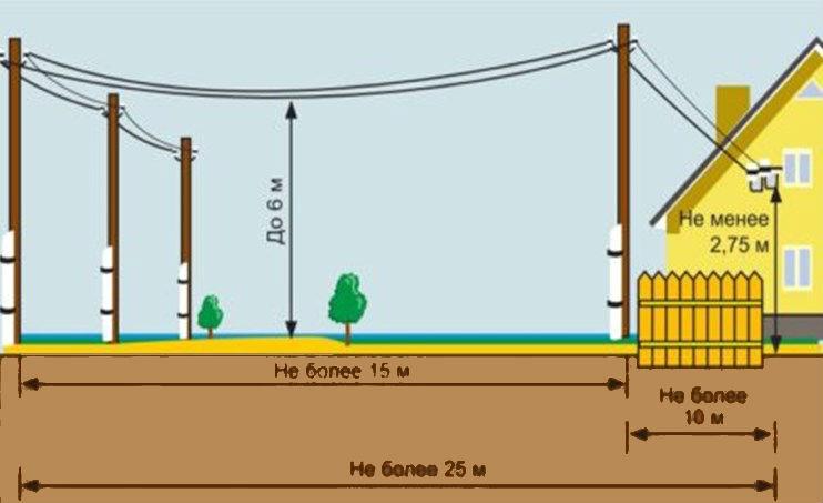

PUE requirements for entering electricity into a private house
According to clause 2.4.57 of the PUE, when laying an air cable parallel to the line of the facade of a private house, it must be removed from it at a distance of at least 20 cm.If there are windows, balconies or terraces in the building in this place, the indicated distance should be at least one meter. All other standardized PUE distances are indicated in the photo on the right. The second option for connecting a power wire for home wiring (in a trench) is extremely rare and therefore is not considered within the framework of this article.
Testing wiring
You can find out whether the scheme for conducting electricity to a private one-story house was correctly developed by testing the finished system. This must be done to make sure that none of its components is overheated, which over time can either disrupt the operation of all electrical wiring, or part of it, or lead to a fire.
To carry out the work, you will need a multimeter that needs to “ring out” all the power lines. The work is divided into several stages.:
- First, you need to check the system for short circuits. Along the way, it is also determined whether there is no contact between the ground wires, phase and zero. When carrying out this work, you should also pay attention to the quality of the insulation, for which you can use a megohmmeter.
- Secondly, checking all switches, both automatic and conventional.
- Thirdly, the next stage is “ringing” all the outputs of the sockets and lamps.
So that after the final commissioning of the network, there are no unforeseen failures, it is better to check the integrity of the electrical cable throughout the house in advance. It may well be that during other work, the wire was mechanically damaged, which would later result either in short circuits or through it at all there will be no power supply.Only after a thorough check of each node and each branch of the electrical network, you can install sockets, lighting fixtures and put it into operation.
Correct planning of electrical wiring in a one-story house is a very responsible job that requires not only basic knowledge, but an understanding of what it should be, and maximum attention at all stages - from circuit to installation.Only in this case, you can be sure that the house is safe for living and is provided with the necessary amount of electricity, taking into account the needs of both its inhabitants and the building itself.
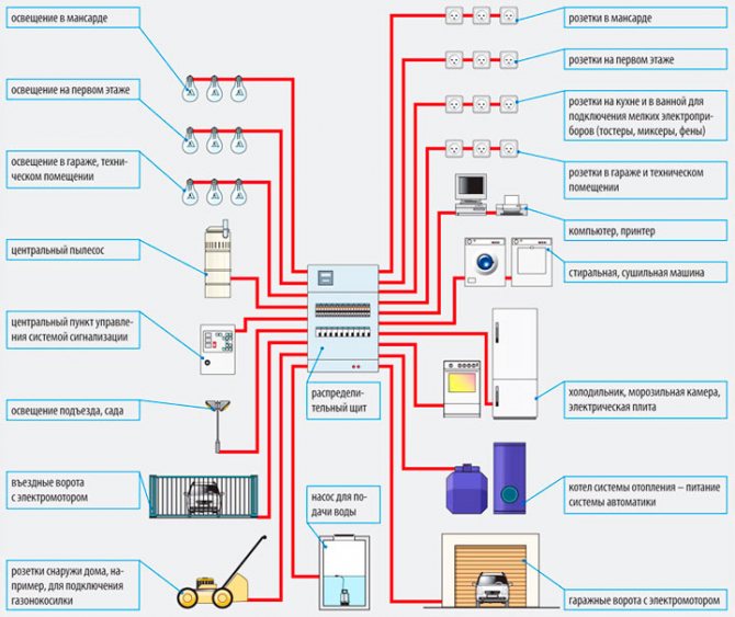
Breakdown of consumers into groups
Before making the electrical wiring with your own hands, you will need to work out the issue of breaking down the consumers in the house into separate groups. His timely and correct decision will help in achieving the following goals:
- Reducing the load on linear taps used to connect individual rooms in a country house.
- Convenient control of loads (their on-line switching on and off) by means of a separate linear automaton.
- Possibility of organizing a multi-level line protection system using several RCDs with different leakage currents.
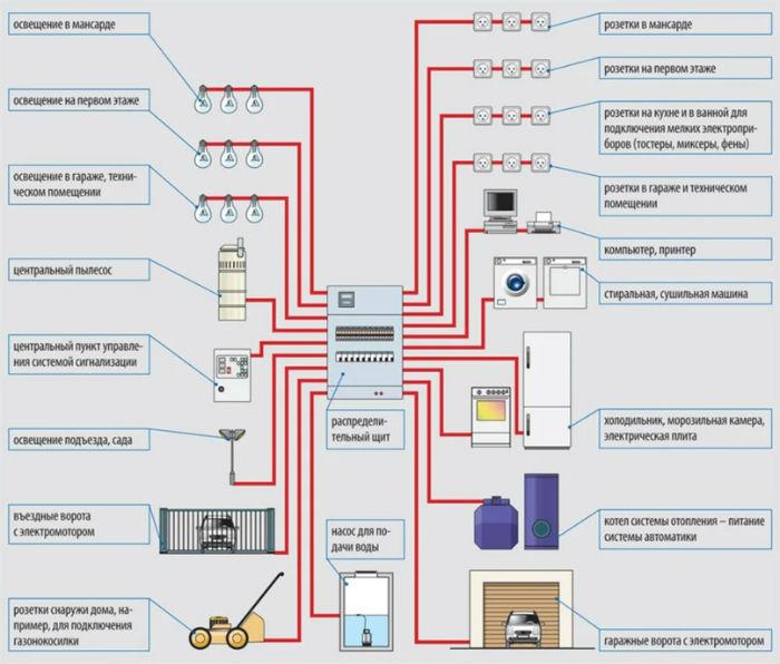

Electricity consumer groups in a private lady
Please note: According to the same PUE, powerful consumers of electricity are connected to an individual linear machine, that is, they are classified as a separate group.
These special loads in the wiring project are traditionally indicated:
- Warm floor.
- Powerful air conditioners.
- Ovens and electric stoves.
- Washing machines and other household consumers with a capacity of up to 10 kilowatts.
In addition, sockets installed in rooms with high air humidity (in bathrooms, in particular, or in basements and attic rooms) are allocated into an independent group. Socket products in several adjacent living rooms can also be combined into a separate group. The same rule applies to all do-it-yourself lighting fixtures (chandeliers, sconces, lighting elements, etc.) mounted in a private house, which are usually divided into two or three subgroups.
Features of wiring in new homes
The wiring, which was done in apartments 40 years ago, was calculated for the operation of a small set of devices - a TV, refrigerator, lighting. Electric stoves, kettles and boilers provided maximum loads.
Today, people buy computers, video surveillance systems, powerful home appliances, wireless communication devices, and more.
At the same time, the principles of designing electrical wiring have not changed, but the network has become more complex and ramified.
Advice! It is important to provide for the optimal number of sockets for appliances that will be used by residents. Otherwise, tees and extension cords will be used, which leads to an increase in loads on individual sections of the wiring and overheating.
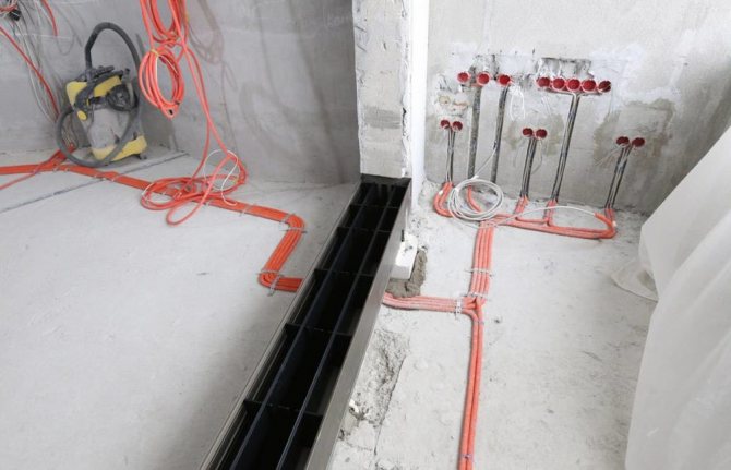

The number of electric points has increased
An additional difficulty in drawing up a wiring diagram is to compare its operating parameters with the power of the devices.
Therefore, you need to know in advance what and where will stand, and what loads will be exerted on the network.
The second point is the correct lighting of the premises, which is carried out in accordance with the norms of SP 52.13330.2016.
Along with the power network, a low-current one is also used in the apartments. These are television and telephone cables, computer equipment, fiber-optic networks, intercoms and acoustics. Physically, they cannot be separated, since the devices are connected to them simultaneously, which means that the position of the tracks is taken into account when drawing up the project.
The amount of cable required to connect all devices has changed significantly. This also applies to lighting.
Previously, rooms were lit with one chandelier, but today spot lighting has come into vogue, which allows you to evenly scatter light over the area of \ u200b \ u200bthe rooms, as shown in the photo below. Each luminaire needs to run a wire.
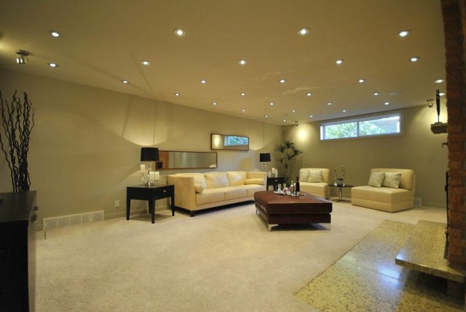

Spot lighting
Interesting to know! Modern electrical appliances are not as voracious as they used to be. Instead of one incandescent lamp, 10 LEDs can work at once, giving much more light. This fact allows you not to overload public networks.
We recommend reading: calculation and design of artificial lighting.
Choosing a cable for wiring
The first thing to decide before starting the installation of the power line is which cable is best suited for laying it inside the house and on the street. To enter into a structure, as already noted, it is most convenient to use a self-supporting SIP wire. For indoor installation, the following types of cable products are optimal:
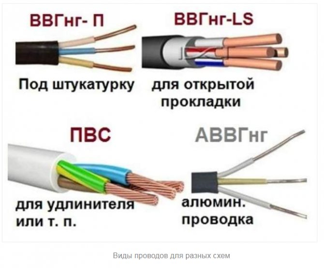
- VVG
- NYM
- PUNP
The main parameters taken into account when choosing a suitable type of product for installing electrical wiring are the number of cores, as well as their cross section.
You can choose the cross-section of the conductors of a wire or cable by power using our online calculator.


Selection of cable cross-section for power and current
On these grounds, each of the listed varieties should be considered separately. The characteristics of the proposed types of wires and cables are as follows.
Typical VVG wire
When arranging wiring, the wiring diagram of which involves the installation of junction boxes, it is most reasonable to choose a VVG cable that works normally at voltages up to 1000 Volts. The number of cores in products of this class varies from one to five, which is quite enough for laying three-phase electrical wiring in a private house (if chosen).
VVG wired products are available in one of the following options:
- in the form of versions with flat or round conductors;
- the same, but with a triangular or square section.
The advantages of this class of cable traditionally include a wide operating temperature range (from -50 ° C to +50 ° C). In addition, the wire is characterized by high strength and moisture resistance. One of the following icons is usually added to the main designation of this product:
- "P"indicating that the cable is flat;
- "Z", indicating that a reinforcing rubber compound is poured between the insulating shell and the outer braid;
- "NG" - a symbol that the insulation of the product is flame retardant.
Additional information: In all VVG cables, with the exception of those marked "З", the space between the outer sheath and the insulation is not filled with anything.
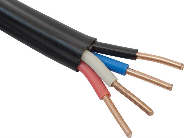

Four-core cable VVG
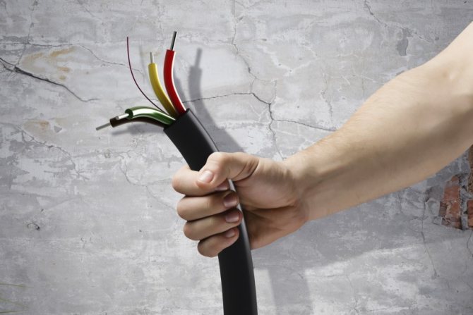
The color of the wires in the cable is distributed as follows. The outer shell of the VVG product is traditionally black, and the color marking of the insulation of the conductive cores is selected in accordance with the current regulations (see the photo on the left). For the installation of the lighting part, a cable with a core cross-section of 1.5 mm2 is used, and when arranging the power supply in private houses, this figure increases to 6 mm2.
When choosing a specific sample of cable products, it is customary to take into account a number of technical considerations, which are as follows. According to the main provisions of the current regulatory documents (PUE, in particular), the selected cable type must meet the following requirements:
- Eliminate the possibility of fire in the wiring.
- Prevent injury to netizens.
- Prevent damage to household appliances connected to it.
To fulfill each of the listed provisions, careful selection of cable products will be required. It is differentiated depending on which part of the chain it is supposed to lay this or that sample. According to this principle, three types of cable products are distinguished:
- wires of brands VVG-2 or VVG-5, having a conductor cross-section of up to 6 mm2 and used to connect a home input to a switchboard;
- cable products called VVG-3 with a conductor cross-section of 2.5 mm2, necessary for laying the main supply lines to power outlets;
- wired products under the designation VVG-3 with a cross-section of 1.5 mm2, used for connecting supply buses to switches and corresponding lighting fixtures.
Taking into account the need to lay all the listed circuits in preparation for installation work, you will have to stock up on the required volumes of each of the names of cable products.
NYM cable
Before choosing a cable suitable for a private house, you should remember about another product under the well-known marking NYM.
This wire with copper conductors is intended exclusively for laying power and lighting lines.
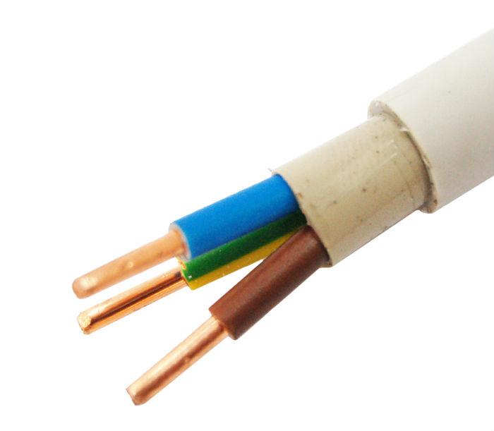

NYM three-core cable
with operating voltage up to 660 Volts. The number of tires differing in color for this product is quite suitable for the stated purposes (it varies from one to five). Their cross-section ranges from 1.5 mm2 to 16 mm2.
The cable is double insulated with a PVC outer sheath and a flame retardant PVC inner braid.
Please note: A significant drawback of this wire for a home electrical network is that it is not protected from ultraviolet radiation, which excludes the possibility of its use in areas exposed to sunlight.
In a situation where there is a choice between the two options considered, preference is usually given to the second, as having the best performance. Since the cost of this cable is somewhat higher than that of VVG, it is wiser to use it only in particularly critical areas of the installation, and to do with a cheaper version on the rest.
PUNP
For those who want to save money on the installation of electrical wiring with their own hands, a budget version of the wire called PUNP is suitable. Products of this type contain two or three copper wires with a cross section of 1.5 to 6 mm2 in double insulation. PUNP, as a rule, is used to connect stationary illuminators and standard sockets.
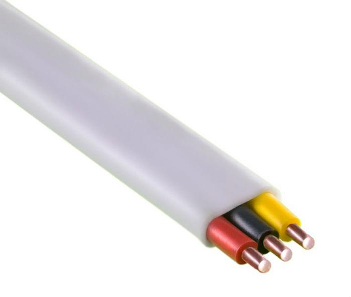

Three-core cable PUNP
In terms of quality, this is not the best choice, especially when wiring is required for many years. Its insulation breaks down easily over time and crumbles when exposed to strong heat.
In addition, it is not suitable in terms of the number of cores for arranging modern three-phase networks with a grounded wire.
Wire section
The cross-section of the wires must correspond to the maximum load in the network. To determine the appropriate section, you should use a special table presented in the PUE.
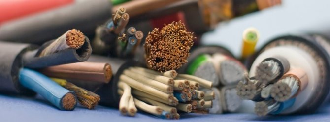

For example, for a current of 16 A, a copper wire with a cross section of 2 mm2 is sufficient. But, experts recommend using a wire with a cross section of 2.5 mm2. For most everyday tasks, this is enough. If the current is 25 A, a copper cable with a cross section of 4 mm2 is required.
Different wires are bought for different groups. For illumination, 1.5 mm2 is usually sufficient. Socket groups are usually connected with 2.5 mm2 wires. Thicker cables should be used for high power consumers.

Drawing up a conditional diagram and plan
Wiring diagrams in a private house, which include distribution boards, are developed individually for each specific building even at the design stage. The specificity of various connection schemes consists in a set of equipment connected to the mains and the lighting system used in the building. Nevertheless, a number of requirements are taken as a basis, which are binding on all designers and users.
According to these provisions and the wiring project, the house network is built according to the following standard scheme:
- The first position, starting from the input, is occupied by an introductory machine, through which it is possible to de-energize the entire power grid at the right time.
- Immediately after it, a typical electric meter is installed.
- Then a circuit breaker common to all lines is mounted.
- And only after that branching into groups of dedicated consumers is organized, in the circuit of each of which a linear AB and a separate RCD are installed.
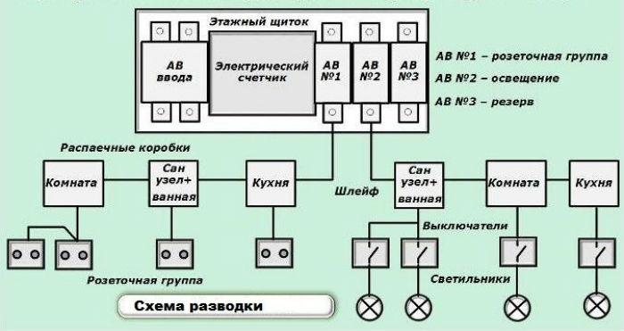

Simplified (conditional) power supply scheme for a private house
Additional information: All listed devices are mounted in the inner spaces of the control cabinet (panel).
A bus wiring is also organized here, allowing you to separate the "ground" (PE) and "zero" (N) lines. These conductors should not intersect at any point and be reliably isolated from one another.
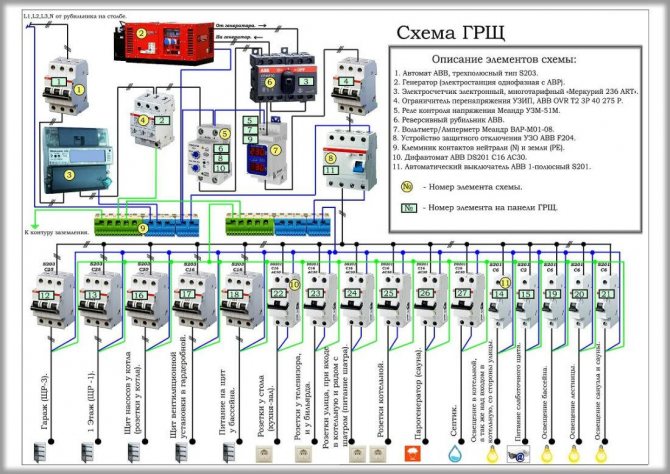

Single-line diagram of the main switchboard
On the Internet, there are a large number of examples of in-house wiring design programs that can help you quickly draw up a wiring plan for the entire building. However, you should be very careful when using such helpers. Potential errors in the home wiring design utility can lead to serious trouble.
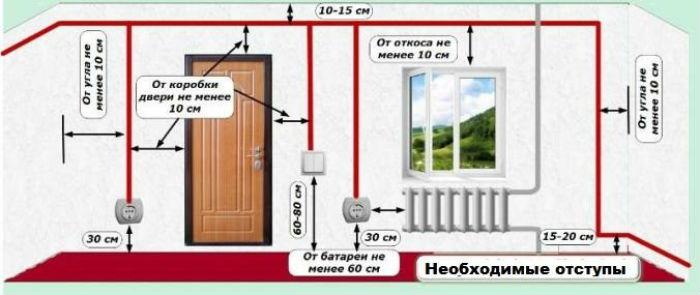

Necessary indents when installing electrical wiring from the floor, ceiling, doors and windows
It also lists the routing paths selected based on the online costing. As an example, consider a wiring diagram in a brick house that connects all of the available "arsenal" of household appliances. Examples of drawing up diagrams and their varieties
First of all, let us pay attention to the fact that there are 5 types of wiring diagrams for any object:
- Basic electrical.
- Mounting.
- Structural.
- Functional.
- United.
All of these varieties are to some extent related to one another. They complement each other, are made according to similar standards and differ only in their purpose. That is why each of these types of circuit solutions needs separate consideration.
Electrical (schematic) diagrams
Principle electrical images are intended to represent the functionality and interaction of the constituent elements of the system, depicted in the sequence of their operation. They visually convey the logic of the electrical circuit in accordance with the features of the circuit drawn on a sheet of paper.
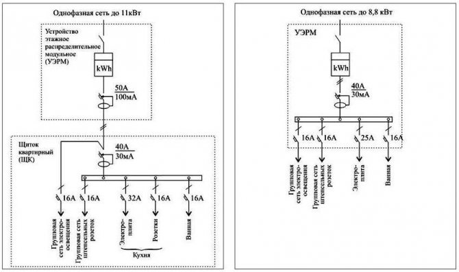

Two simple electrical circuits for the power supply of a private house with a supply voltage of 220V
Important! To prepare such images, special graphic icons are used, which in most cases differ from the symbols used in drawing up other schemes.
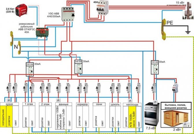
A sample wiring diagram for a private house with a 380V supply voltage is shown in the photo below.
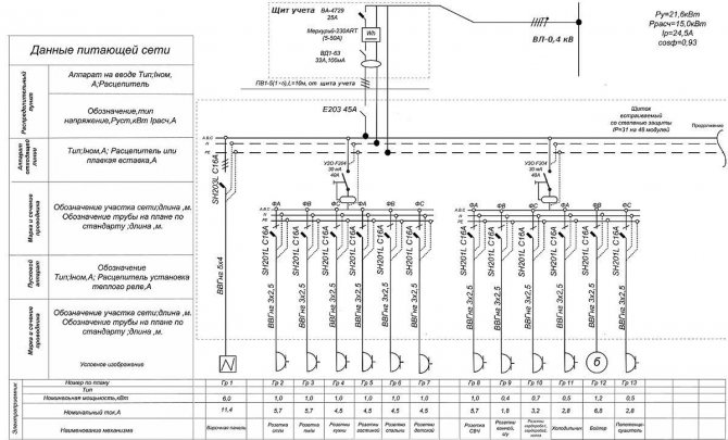

Electrical schematic diagram of the supply and distribution network
This view shows the connection diagram of the power cable to the power supply system. It shows that the house uses a three-phase 5-wire system containing a separate grounding conductor. In addition, such mandatory elements of electrical wiring are shown in it in the legend, such as:
- Introductory machine.
- Typical electric meter.
- RCD.
- Linear machines for each load group (garage, kitchen, lighting, etc.).
Wiring diagram
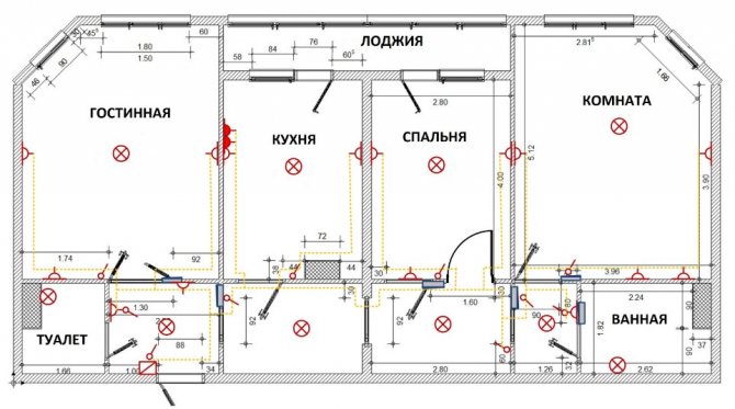
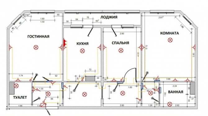
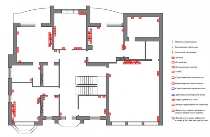
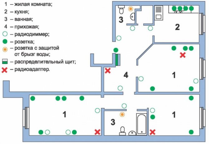
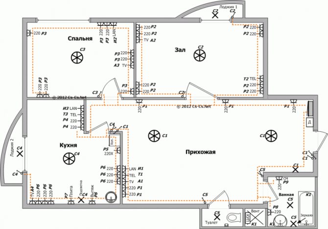
Wiring diagrams are prepared in the form of drawings or sketches of individual elements of electrical equipment. According to them, the installation of the entire power supply system of the house is organized. In them, in the form of conventional icons, the location of individual elements is taken into account, and all electrical connections between them are displayed. It is important to know that wiring diagrams are created on the basis of schematic diagrams and contain all the necessary information on the design of the system, including how to make electrical connections. An example of its implementation with reference to the layout of the house is given below.
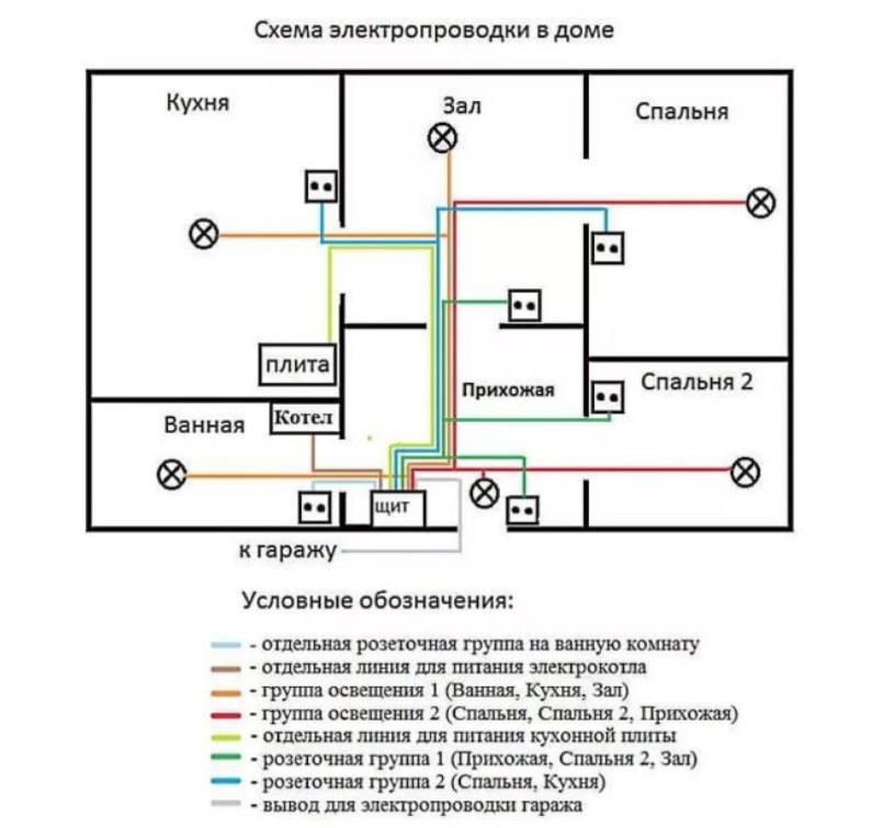

Wiring diagram of electrical wiring with reference to the layout of the house
The diagram clearly shows not only the connections between the electrical elements of the system. Here you can see the places where individual equipment samples are installed. In addition, according to this scheme, it is possible to obtain information on the breakdown of consumers into separate groups.
Structural and functional
This type of drawing document allows you to get a general idea of how the electrical network works with the equipment connected to it and what is included in it. The graphic representation of the elements of the electrical circuit conveys an overall picture of what operations will be required to proceed to the next stages of work (connection and configuration). The order of reading the structural document is supplemented with special pointers (arrows) and explanatory inscriptions, which guarantee an understanding of the essence of the work of the scheme. Thanks to the detailed structuring of the order of operation of electrical circuits, any novice master will be able to understand it.
A functional electrical circuit is inherently not too different from its structural counterpart. The only difference between these two documents is that the second provides a more detailed description of the individual chain nodes associated with their functional purpose.
Combined schema
The last of the electrical documents used in distribution and household networks is a combined diagram that includes several types of drawings at once. It is in demand in a situation where it is necessary, without complicating the graphic images, to designate all the important details of the circuit, emphasizing their specificity. The type of circuits under consideration is most often drawn up when arranging branched electrical networks in large residential buildings such as multi-storey mansions. An ordinary home craftsman may be interested in such documents only from the point of view of broadening his horizons. Their approximate form is shown in the figure below:
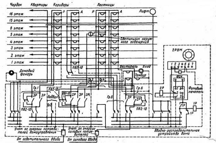

Combined power supply scheme
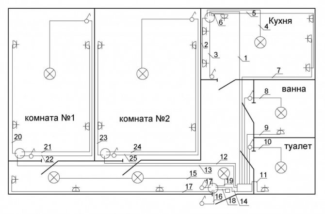
Also known are schematic representations of cable routes, which are reduced to transferring to the drawing a simplified procedure for wiring a line from switchboards to each individual consumer. In essence, they are similar to an electrical wiring diagram, since with its help it is easier for workers to figure out how to organize the wiring between two points.
Wiring diagram
First you need to draw up a detailed wiring diagram. Here it is necessary to provide for each device connected to the mains, starting from the switchboard. The scheme provides for all protective equipment, circuit breakers, voltage relays, etc.
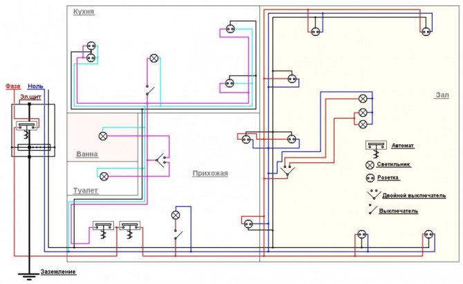

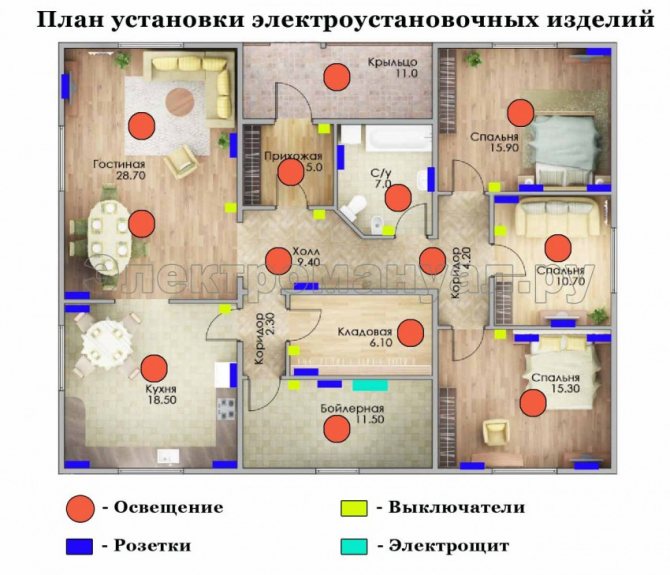
Places for laying wires, mounting sockets, switches and lighting devices also need to be reflected in the diagram. Consumers need to be divided into groups. Each group must have a separate machine.
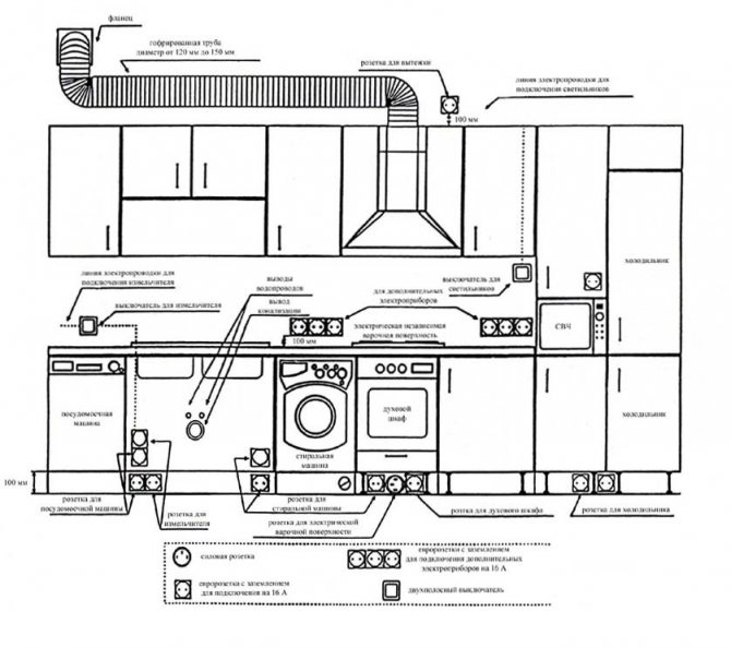

Diagrams and examples of installation can be found in the do-it-yourself photo of the wiring. You can use one of the ready-made schemes, adapt it to your own needs, or draw up a completely new plan from scratch.
The procedure for installing electrical wiring step by step
This chapter will consider the question of how to properly lay the wires when carrying out the entire range of electrical work. As a rule, the installation of electrical wiring begins with the preparation of the premises available in the house for its laying.
Installation of hidden wiring in the video
Electrical installation in the apartment
Installation of electrical wiring
Installation of hidden wiring
How to conduct hidden electrical wiring
Please note: When drawing up step-by-step instructions for installation work, the chosen method of installation must be taken into account: in the thickness of the walls or on their surface.
When choosing, one should be guided by the main provisions of the PUE, which stipulate the possibilities of applying one or another option. So, clause 7.1.39 of this document imposes restrictions on the use of open cable laying in places where food is prepared (in the kitchen, in particular). For these purposes, a harness with conductors hidden in the thickness of the walls must be mounted in this part of the room.
In all other areas of the kitchen space, it is allowed to use the same wiring method as in all other living quarters. The exception is special rooms with high air humidity (baths, showers and the like).
Additional information: If there is an RCD protective device in the power circuit, the PUE rules allow the use of a cable with an appropriate degree of protection against climatic factors.
The general installation procedure is described by the following sequence of actions:
- First, according to the prepared wiring diagram, the marking of the cable or bundle route is made on the walls of the rooms (depending on the chosen laying method).
- With the hidden method, grooving of grooves is carried out in the marked areas, for which either a grinder or a special tool is used - a groove cutter.
- Then, sections of a wire harness or a VVG cable, previously measured along the length of the cable, are placed in the grooves, the ends of which are cut at the end sections and brought out.
- When sealing the joints of wires with terminals of wiring products, special insulating means (electrical tape, for example) are traditionally used.
- After the conductors are fixed in the grooves with special brackets or alabaster, you can proceed to sealing the strobes for electrical wiring.
- For this, a previously prepared finishing plaster is used.


The device of grooves (grooves) for laying and fixing electrical wiring
There are many different fasteners for fastening the cable, the appearance of which is shown below.


Cable tie, universal fastener for securing conductors
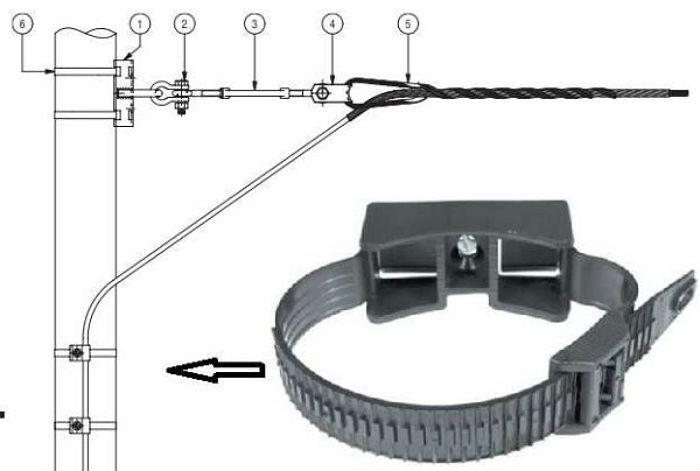

The cable tie is designed for fastening the cable on concrete and brick foundations


Metal clip for cable fastening
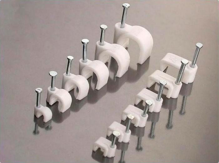

Plastic bracket for cable fastening


Electrical insulator for fastening retro wiring


Dowel tie for fastening wiring or cable products


Dowel clamp for fixing flat and round cables
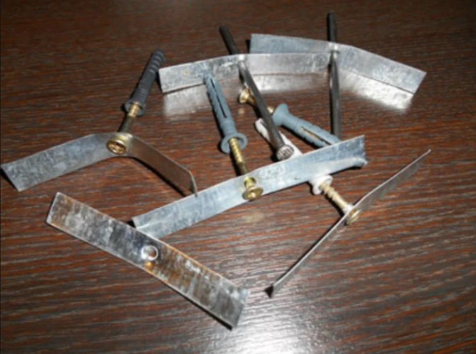

Homemade steel tape fasteners
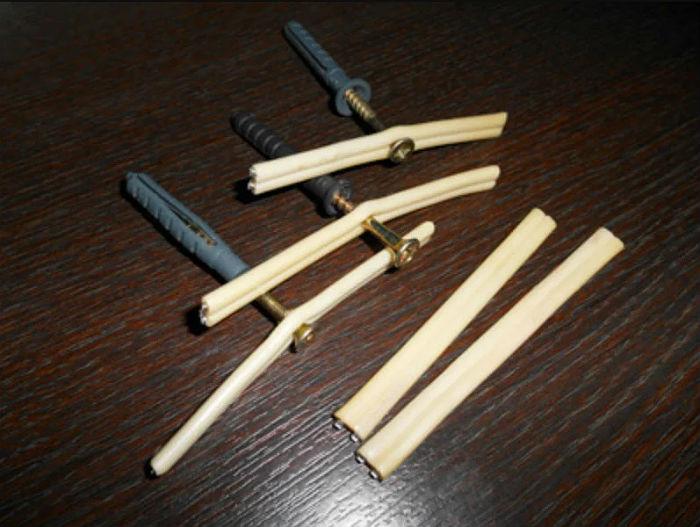

Homemade fasteners from pieces of wire
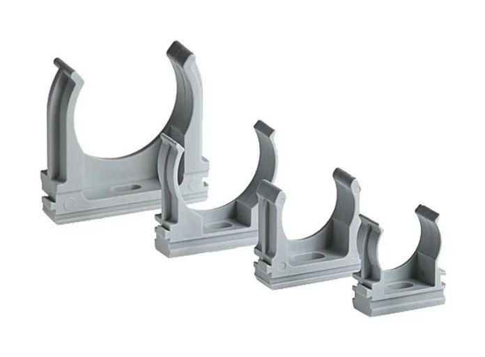

Plastic clips for attaching a round cable or corrugated pipe
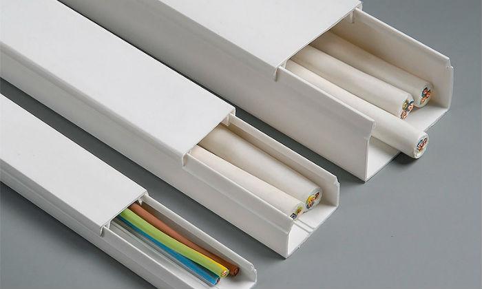

Plastic cable duct
Upon completion of work with the wires (cable), you can proceed to the installation of wiring accessories (junction boxes, switches and sockets). When installing them, it is important to strictly follow the wiring diagram, which clearly reflects their relative position.Before installing the junction box, for example, it is important to make sure that it is located directly above the outlet and as close as possible to the lighting device (chandelier). If everything is done correctly (according to the wiring diagram), as a rule, there are no questions about what the junction box is for.
Installing socket boxes and chipping walls on video
Installation of socket outlets in a concrete / brick / aerated concrete wall. Overview of crowns.
Wall slitting
Recall that according to clause 7.1.40 of the PUE, in baths, saunas, shower rooms and similar rooms, only open electrical wiring with junction boxes located on the wall surface is allowed.
In addition, the installation of an RCD is required in these rooms. Upon completion of the installation of all wiring products, it remains only to connect them to the previously removed ends of the harnesses or cable strips.
Assembling the wiring diagram and connecting the wires in the video
Electrical installation. Part 1 - Wiring Diagrams for Dummies
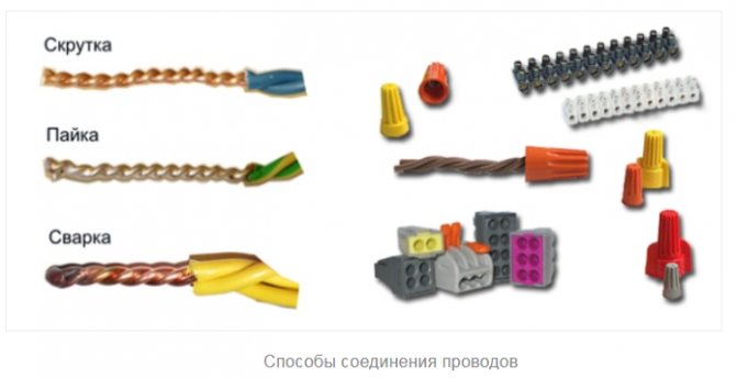
Electrical installation. Part 2 - Ways to connect conductors
Electrical installation. Part 3 - Welding conductors
Wiring in the bathroom
For the bathroom, it is not advisable to carry out separate branches, therefore, most often they use part of the contour from the kitchen. This is due to the fact that, according to safety rules, this room should only have lighting, and it is indicated on the official wiring diagram of the electrician. Therefore, it shows where the luminaire will be located and the route of the cable to it.
But, as often happens, people install a boiler, washing machine and other equipment in the bathroom, so they do not indicate it in the plan in order to avoid problems with putting the house into operation.
- To do this, use an extension cord with three sockets, from which a three-core cable departs.
- Above the plinth between the bathroom and the kitchen, you need to drill a hole into which you can stretch the extension cord and cables from the boiler and washing machine.
- Supplied in advance with three-pole plugs, these cables from the appliances and the extension cord are connected to the circuit in the kitchen, and so that they are not visible, they can be “packed” in a drywall box.
In the bathroom itself, it is better to fix the extension cord on the wall, for example, hang it on screws. One or two devices can be permanently connected to an extension cord, and the third can be used for small household appliances, for example, a hair dryer, a fan or other.
Outdoor wiring
Unlike city apartments, where all the wiring is located within the dwelling, in a country house there are plots (annexes such as a garage, for example, or utility workshops) located outside the house. In this case, the wiring being laid is exposed to all sorts of factors, including climatic ones, and therefore needs additional protection.
Installation of external wiring
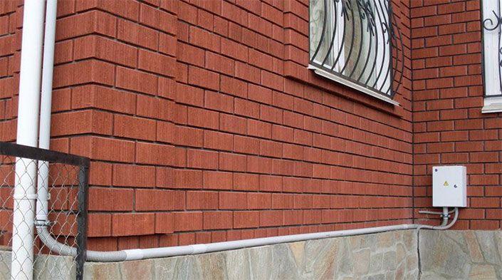

External wiring on a brick facade in a corrugated pipe
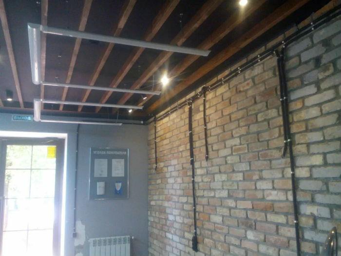

Outdoor open wiring in the annex
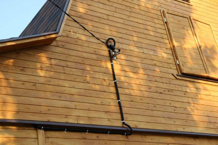

Outdoor wiring on a wooden wall
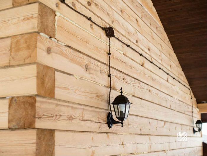

Installation of electrical wiring on an external wooden wall
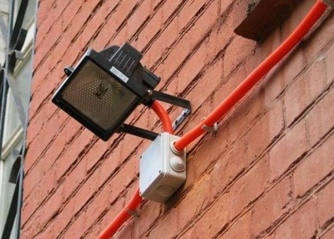

Mounting the spotlight on an external brick wall
Wiring in rooms located outside a residential building is allowed to be installed in metal cable ducts or pipes through wooden partitions and floors of the house. If, according to the conditions of installation work, metal pipe products are not used, special steel sleeves must be installed in the places where the cable passes through walls and partitions. With their help, it is possible to reliably protect the wires from mechanical deformation.
Important! According to the requirements of the PUE, it is strictly forbidden to use new plastic materials that spread combustion well for these purposes.
The wiring diagram containing the routes for laying wires along the facade of buildings allows the use of not only metal pipes, but also steel twisted corrugations to protect them. Immediately, we note that for the external surfaces of buildings, finished with coatings of flammable and combustible materials, this method is considered the only acceptable one. For facades of buildings covered with fireproof finishing materials, an open installation method using plastic corrugation is possible.
In all cases, the mechanical protection of the cable does not exclude the need to seal the sheath, excluding the possibility of even small amounts of vapors and moisture getting inside.
Additional information: In the case when it is planned to make a layout of the ground lighting route outside the house, a drainage system must be installed for areas in contact with the ground.
This technical measure significantly reduces the likelihood of moisture accumulation in the area where street lamps are located. When choosing a brand of a wired product that is suitable for these purposes, it is usually assumed that it has appropriate protection. For outdoor installation, it must be at least IP44.
In conclusion, we note that the installation of electrical wiring in a private house is a rather complicated procedure in order to deal with it without special training. To obtain the desired result, you will need to familiarize yourself with all the materials presented here, as well as master the basic techniques of working with electrical components and power equipment.
Do-it-yourself wiring in the apartment
The equipment is being installed according to the developed scheme. There are many subtleties involved in this process. We advise you to entrust this matter to an electrician, but everyone is obliged to know about the most common mistakes in order to be able to control the work of hired personnel.
- Wiring is only done horizontally and vertically. Oblique sections of the route will help save wires, but can become a serious problem in the future, when the wiring is inadvertently punctured by a puncher.
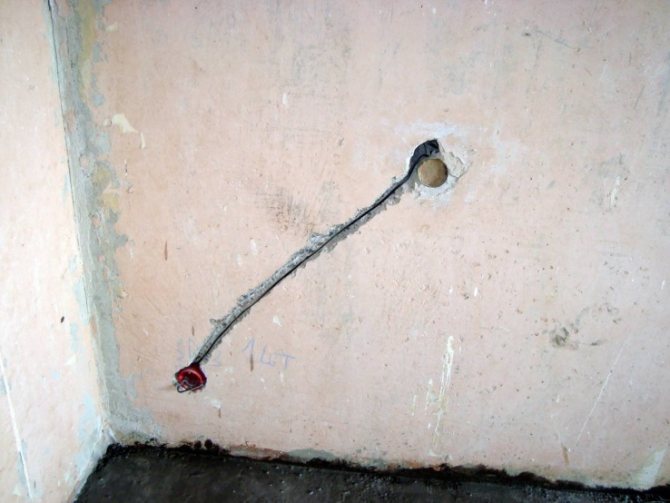

Such cable laying is not allowed. - Junction boxes should always be left in plain sight, as they may need to be accessed at any time.
- Avoid daisy chaining outlets whenever possible.
- The cables must be sunk into the plaster to a depth of at least 2 centimeters. Otherwise, if a short occurs, the finish may light up.
- When laying a cable on combustible structures, we place it in a metal pipe, possibly corrugated. This is a special fire safety requirement, which is rarely observed in practice, and completely in vain.
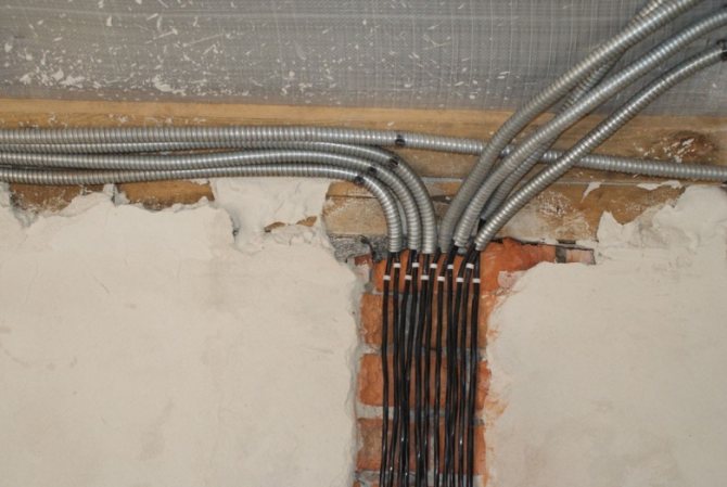

On the boards, the cable is laid in a metal corrugation. - Electric wires, even laid in corrugation, must not be connected to conductive supporting structures. These include a frame for plasterboard walls and ceilings.
- When installing sockets and switches on combustible walls, non-combustible material, for example, paronite, is laid under their boxes.


Cushioning paronite sheets


